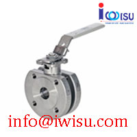
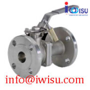
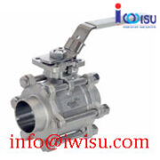
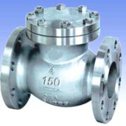
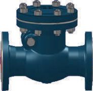
Ball valves Series 80D
1. General
To protect the ball and seats prior to installing the valve, flush out the pipes, making sure all sediment and welding residue have been removed.
The ball valves are not suitable to work with abrasive media because seals and seats may be destructed.
Please refer to the prospectus “WAFER (Compact) BALL VALVES SERIES 80D” for dimensions, materials, replacement parts and working conditions. The runner of the installation is responsible for the choice of the materials.
2. Installation
The direction of flow and the installation position of the Ball Valves are free. The runner of the installation or the assembling company is responsible for the selection and the installation of the seals between the ball valve and the counter flanges of the pipe. The assembling must be performed under acceptance of the regularizing of the technology. Remove the plastic protective covers before installing the valve.
The standard ball valve can be distinguished because of his grey handle; the sizes DN 15 up to DN 80 are equipped with 2 PTFE body seals (5 +22) and 1 PTFE stem packing (8/9). The size DN 100 is equipped with 1 body seal (5).
The firesafe design ball valve can be distinguished because of stamp marking “AF” on flange ends; the sizes DN 15 up to DN 80 are equipped with 1 PTFE body seal (22), with 1 graphite body seal (5) and with 1 graphite stem packing (8/9). The size DN 100 is equipped with 1 body seal (5).
Remove the plastic protective covers before installing the valve.
The ball valve will be placed between 2 counter flanges. The tightening torques of the flange screws depends on the used sealing materials.
Data Download: prospekt_80D_e
3. Replacement of seats and seals
Before removing the ball valve, make sure this is cold and no longer under pressure. For internal pressure relief, open and close the ball valve once. Only original repair kits may be used.
Unscrew the insert (2) with an appropriate tool. Turn handle (15) into closed position and remove the ball (3). Take out the body seals (5/22) and seats (4). Remove handle (15) or actuator, open and remove lock saddle (12), remove stem nut (13), Belle ville washers (11) and stem seal follower (10). Strike stem (7) gently with a nylon hammer from outside into the body and take the stem out of the body. Remove stem packing (9) and stem seal (6). Clean stem (7) and body (1) from any residue.
4. Assembly
Only clean, undamaged and parts in good conditions may be used. Push stem seal (6) and O-Ring (21, optional) onto stem (7). Check correct function of the 2 antistatic devices (20). Grease stem (7) with suitable grease and insert from the inside of the body (1). Insert the stem packing (9). In case of a graphite stem packing, tighten the packing with an assembly sleeve. Put on stem seal follower (10), Belleville washers (11) and saddle lock (12). Tighten the stem nut (13) to the torques from table 1; secure stem nut (13) with the saddle lock (12). Put on washer (14) and, place handle (15) and tighten the counter stem nut. Open the ball valve with handle (15) and check correct operation. In order to reduce the running moment between ball and seats we recommend to grease the seats (4) lightly with a suitable grease. Insert the cleaned ball (3), the seats (4) and the body seals (5/22) into the insert (2).
Grease the thread of the insert part (2) with suitable grease (in order to avoid thread blocking); screw tight the insert (2) very cautious and without hurting the seals (5/22). Carefully flush the pipe before installing the ball valve into the pipe. Place the ball valve between the counter flanges of the pipe work, place appropriate seals between the flanges and fasten the screws M.
5. Operation
During operation the ball valve may not be dismantled nor the screws M may be changed. Putting into operation , the ball valve must be checked for proper function; if there are doubts of proper function change the ball valve
6. Maintenance and storage
The ball valves require no special maintenance if they are correctly laid out, the installation instructions carefully followed and only operated in the open or closed position (wearing parts such as seats and packing are excluded).
In case of leakage to the outside, replace the body seals (5/22) respectively the seats (4). Replace the stem packing (9) and tighten the stem nut (13). If tightness cannot be achieved, then the defective parts must be replaced according to the instruction item 3.
The ball valves must be stored in open position and protected against dust and damage.

